13 min read
Bathroom exhaust ventilation is an essential part of residential HVAC design. Bathrooms generate moisture, odors, and airborne contaminants during everyday activities such as showering and bathing. Without effective ventilation, excess moisture can contribute to condensation, mold growth, and damage to building materials.
For MEP engineering firms, designing a bathroom exhaust system involves more than selecting an exhaust fan. Engineers must determine the required airflow, select suitable equipment, size and route the exhaust duct, account for system resistance, and identify an appropriate outdoor termination location.
A well-designed system removes moisture at the source while operating reliably and quietly. This guide explains how MEP engineers can design bathroom exhaust ventilation for single-family homes in the United States.
What Is Bathroom Exhaust Ventilation?
Bathroom exhaust ventilation is a mechanical system that removes indoor air containing moisture, odors, and other contaminants from a bathroom and discharges it outdoors.
A typical residential bathroom exhaust system includes:
- An exhaust fan
- An intake grille
- An exhaust duct
- Duct fittings and connections
- A backdraft damper, where required or provided
- An exterior wall or roof termination
- Electrical wiring and operating controls
When the fan operates, it draws air from the bathroom through the grille and moves it through the duct to the exterior.
The system should be designed to deliver the required airflow under the actual installed conditions, not simply based on the fan’s maximum advertised airflow.
Why Is Bathroom Exhaust Ventilation Important?
Proper bathroom exhaust ventilation supports indoor air quality and helps manage moisture in residential buildings.
1. Controls Excess Moisture
Showers and baths release water vapor into the indoor environment. If this moisture remains in the bathroom, it can condense on mirrors, windows, ceilings, and exterior walls.
An appropriately designed exhaust system removes moisture-laden air and helps limit prolonged periods of high humidity.
2. Reduces the Risk of Mold Growth
Persistent moisture can create conditions that support mold growth on susceptible surfaces.
Bathroom exhaust ventilation helps remove moisture at its source. However, ventilation should be combined with effective moisture control, appropriate insulation, air sealing, and correction of any water leaks.
3. Removes Odors and Airborne Contaminants
Bathroom exhaust systems remove odors and help reduce the accumulation of contaminants generated during normal use.
Effective local exhaust is particularly important in bathrooms without suitable natural ventilation or where the applicable code requires mechanical exhaust.
4. Protects Building Materials
Repeated condensation can damage paint, drywall, wood finishes, and other moisture-sensitive materials.
A properly designed ventilation system helps reduce the likelihood of moisture-related damage, although it cannot compensate for building envelope leaks or other sources of persistent water intrusion.
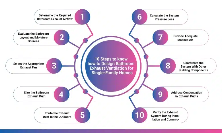
10 Steps to know how to Design Bathroom Exhaust Ventilation for Single-Family Homes
Step 1: Determine the Required Bathroom Exhaust Airflow
The first step is to establish the minimum exhaust airflow required for the bathroom.
Airflow is commonly expressed in cubic feet per minute (CFM). The required rate depends on the applicable residential code, ventilation standard, system operating mode, and project requirements.
For example, the 2024 International Residential Code (IRC), Section M1505.5, lists the following minimum local exhaust capacities for bathrooms and toilet rooms in one- and two-family dwellings:
| Operating mode | Minimum exhaust capacity |
| Intermittent operation | 50 CFM |
| Continuous operation | 20 CFM |
These values are specific to the cited code provision. The engineer must confirm the code edition adopted by the project’s jurisdiction and check all applicable conditions before using them for design.
Intermittent Exhaust
An intermittent exhaust fan operates when needed, commonly through a wall switch, timer, occupancy sensor, or humidity control.
Because the fan operates for limited periods, the required airflow is typically higher than the rate used for continuous operation under the cited IRC provision.
Continuous Exhaust
A continuous exhaust system operates for extended periods to provide ongoing local exhaust.
Continuous operation may require lower airflow at any given moment, but the system must meet the applicable continuous ventilation requirements and operate as intended.
Important: Do not choose the fan based on a general rule alone. Confirm the required airflow, operating mode, controls, and code provisions for the specific home.
Step 2: Evaluate the Bathroom Layout and Moisture Sources
Before selecting equipment, review the architectural floor plan and identify the bathroom’s layout.
Important considerations include:
- Bathroom floor area and ceiling height
- Location of the shower or bathtub
- Toilet and lavatory locations
- Door position and available air transfer paths
- Exterior walls and roof access
- Distance to a suitable outdoor termination
- Available ceiling or attic space
- Potential conflicts with framing and other building systems
The exhaust grille should be located to capture moisture effectively without creating unnecessary airflow restrictions.
For many layouts, placing the exhaust pickup near the shower or bathtub can improve local moisture removal. The final location should account for the bathroom geometry, fan arrangement, manufacturer instructions, and electrical safety requirements.
Step 3: Select the Appropriate Exhaust Fan
After establishing the required airflow, select a fan capable of delivering that airflow under the expected system resistance.
Check the Fan’s Airflow Rating
Manufacturers may publish airflow ratings at different static pressures. A fan’s advertised airflow at low resistance may not represent the airflow it will deliver after installation.
The selected fan should meet the required airflow at the design operating point.
For example, if a design requires 50 CFM, a fan labeled with a nominal rating of 50 CFM should not automatically be assumed to deliver 50 CFM through every duct configuration.
Consider Static Pressure
Static pressure represents the resistance the fan must overcome to move air through the system.
Resistance can result from:
- Duct length
- Duct diameter
- Elbows and bends
- Transitions and fittings
- Backdraft dampers
- Exterior termination fittings
- Other components in the airflow path
The fan selection should be based on the expected pressure loss of the complete installation.
The 2024 IRC also specifies a minimum static pressure condition for bathroom exhaust fan capacity ratings in its applicable provision. Refer to the adopted code for the precise requirement.
Review Noise Levels
Bathroom exhaust fans are commonly selected with noise ratings expressed in sones.
A lower noise rating may improve occupant comfort and encourage regular use. However, the selected fan must still meet the required airflow and pressure conditions.
Consider Controls and Energy Use
Depending on the project, the exhaust fan may use a manual switch, timer, humidity sensor, occupancy sensor, or continuous-operation control.
The control strategy should support the required ventilation operation and allow occupants to use the system appropriately.
Step 4: Size the Bathroom Exhaust Duct
Duct sizing affects airflow, pressure loss, noise, and fan performance.
The duct must be large enough to convey the required airflow without creating excessive resistance.
Consider the Required Airflow
Higher airflow generally requires a duct arrangement capable of carrying more air without excessive velocity or pressure loss.
The engineer should use the selected fan’s airflow requirement and performance data to establish the duct design.
Evaluate Duct Diameter
A smaller duct generally creates greater resistance at a given airflow than a larger duct of otherwise comparable characteristics.
Using an undersized duct can reduce delivered airflow, increase fan noise, and make the system less effective at removing moisture.
However, the largest possible duct is not always necessary. The final diameter should be based on the design airflow, duct material, routing, pressure loss, available space, and manufacturer requirements.
Account for Duct Length
Long duct runs create additional friction losses.
Where practical, the design should minimize unnecessary duct length and avoid complicated routing. This is particularly important when a bathroom is far from an exterior wall or when the exhaust duct must pass through an attic.
Minimize Unnecessary Bends
Elbows, sharp turns, and abrupt transitions can increase resistance.
The design should use a practical route with the fewest unnecessary bends while still respecting the building layout and installation constraints.
Follow Manufacturer Requirements
The fan manufacturer’s instructions may specify duct diameters, connection details, allowable installation arrangements, and other requirements.
These instructions should be checked alongside the applicable code and the design airflow calculation.
Step 5: Route the Exhaust Duct to the Outdoors
Bathroom exhaust air should be discharged to an approved outdoor location in accordance with the applicable code and product instructions.
It should not be discharged into an attic, crawlspace, ceiling cavity, or another concealed building space where moisture can accumulate.
Roof Termination
A roof termination may be suitable when the bathroom is near an accessible roof route.
The design should account for roof construction, weather protection, flashing, termination resistance, and coordination with other rooftop components.
Exterior Wall Termination
A wall termination may be practical when the bathroom is located near an exterior wall.
The engineer should verify that the termination location complies with applicable requirements and does not create problems with windows, outdoor-air intakes, neighboring properties, or other openings.
Prevent Backdrafts and Water Entry
The termination assembly should be appropriate for the application and installed according to the manufacturer’s instructions.
A suitable backdraft damper can help prevent unwanted reverse airflow when the fan is off. The design should also address weather exposure and water entry.
Step 6: Calculate the System Pressure Loss
Once the fan, duct size, and routing have been selected, evaluate the total resistance of the exhaust system.
The calculation should consider the complete airflow path, including relevant components.
A typical pressure-loss review includes:
- Straight duct friction
- Elbows and fittings
- Duct transitions
- Dampers
- Exterior termination fittings
- Other components specified by the manufacturer
The calculated system resistance is then compared with the fan’s performance data to verify that the required airflow can be delivered.
This step helps prevent a common design problem: specifying a fan with an adequate nominal CFM rating but installing it in a duct system that restricts its actual performance.
Step 7: Provide Adequate Makeup Air
When an exhaust fan removes air from a bathroom, replacement air must enter the room.
If the bathroom is tightly sealed and there is no suitable air transfer path, the fan may struggle to deliver its intended airflow.
Makeup air can enter through a suitable undercut door, transfer opening, or another designed air pathway, depending on the building configuration and applicable requirements.
MEP engineers should consider the following:
- Door undercut and transfer-air provisions
- Air transfer from adjacent spaces
- Effects of other exhaust equipment
- Building airtightness
- Pressure relationships within the home
The replacement-air path should not compromise required fire, smoke, acoustic, or other separation provisions.
Step 8: Coordinate the System With Other Building Components
Bathroom exhaust ducts often pass through ceiling cavities, wall framing, attic spaces, or roof assemblies.
The design should be coordinated with the architectural and structural layout before construction documents are finalized.
Key coordination items include:
- Ceiling joists and roof framing
- HVAC supply and return ducts
- Plumbing vent piping
- Electrical wiring and fixtures
- Insulation and air barriers
- Recessed lighting and ceiling fixtures
- Access for installation and maintenance
Early coordination can reduce field changes and prevent conflicts that make the duct difficult to install.
Step 9: Address Condensation in Exhaust Ducts
Bathroom exhaust air contains moisture. If warm, humid air travels through a cold duct surface, condensation may occur.
This can be a concern when ductwork passes through an unconditioned attic or other cold space.
Depending on the climate and system arrangement, the design may need to consider:
- Suitable duct insulation
- Proper duct routing
- Sealed duct joints
- Weatherproof exterior termination
- Installation practices that prevent water accumulation
- Compliance with manufacturer instructions and applicable codes
The design should also avoid duct arrangements that create low points where condensate can collect.
Insulation requirements depend on the project conditions and applicable standards. They should not be applied as a substitute for correct duct routing and installation.
Step 10: Verify the Exhaust System During Installation and Commissioning
A completed design should be checked to confirm that the installed system performs as intended.
Depending on the project requirements, verification may include:
- Confirming the correct fan model and installation
- Checking duct diameter and routing
- Inspecting duct joints and connections
- Verifying the outdoor termination
- Checking controls and operating modes
- Measuring delivered airflow where required
- Confirming that air can transfer into the bathroom
- Reviewing noise or vibration concerns
Airflow should be measured using an appropriate method and compared with the design requirement.
If the delivered airflow is below the target, investigate possible causes such as duct restrictions, installation errors, excessive system resistance, a blocked termination, or inadequate makeup air.
Common Bathroom Exhaust Ventilation Design Mistakes
Selecting a Fan Based Only on Its CFM Label
The rated airflow may not reflect actual performance at the installed system resistance. Fan selection should account for the duct layout and pressure loss.
Using an Undersized or Overly Restrictive Duct
An unsuitable duct size can reduce airflow and increase noise. Duct diameter should be selected based on airflow, resistance, and manufacturer requirements.
Discharging Exhaust Air Into the Attic
Discharging humid bathroom air into an attic can increase moisture-related problems. The system should terminate at an approved outdoor location.
Designing an Excessively Long Duct Route
Long runs and unnecessary bends can increase pressure loss. Efficient routing helps the fan deliver the intended airflow.
Ignoring Makeup Air
A bathroom without a suitable replacement-air path may not receive the designed exhaust performance.
Overlooking Condensation Risk
Ductwork in cold or unconditioned spaces may require insulation and careful routing to reduce condensation concerns.
Failing to Coordinate With Framing and Other MEP Systems
Uncoordinated duct routing can result in conflicts with structural framing, HVAC equipment, plumbing pipes, electrical systems, or ceiling fixtures.
Skipping Performance Verification
A fan that runs does not necessarily deliver the required airflow. Where required, the installed system should be tested and verified.
How Revit MEP and BIM Support Bathroom Exhaust Design
Revit MEP and BIM workflows can help engineering teams develop coordinated bathroom exhaust layouts for single-family homes.
Depending on the project scope, BIM can support:
- Modeling exhaust fans and duct routes
- Coordinating ducts with ceiling and roof framing
- Reviewing clearances around fans and access points
- Checking routing conflicts with plumbing and electrical systems
- Coordinating roof and wall terminations
- Preparing ventilation drawings
- Updating layouts after design revisions
- Identifying installation constraints before construction
BIM supports design coordination, but it does not replace airflow calculations, fan performance checks, or verification of code compliance.
MEP engineers must still establish the required airflow, evaluate system resistance, select appropriate equipment, and verify the final design.
How MVN Engineering Supports Residential HVAC Design
U.S. MEP design firms may require additional engineering and BIM production capacity to complete residential HVAC layouts and construction documentation.
MVN Engineering Services supports MEP firms with HVAC Design and MEP design-related production, including:
- HVAC duct layout drafting
- Residential ventilation system documentation
- Revit MEP modeling
- HVAC and plumbing coordination
- BIM clash detection
- Drawing updates based on engineering markups
- Coordinated construction documentation
- MEP production support
By working with the project’s design criteria, architectural plans, engineering markups, and established workflows, MVN can support residential design teams that need reliable documentation and coordination assistance.
Conclusion
Designing bathroom exhaust ventilation for single-family homes requires careful consideration of airflow, fan performance, duct sizing, pressure loss, makeup air, and outdoor termination. Each component affects how effectively the system removes moisture and odors from the bathroom.
For MEP engineers, the process should begin with the applicable ventilation requirements and continue through equipment selection, duct routing, pressure-loss evaluation, and performance verification. Coordinating the exhaust system with framing, insulation, electrical services, and other HVAC components also helps reduce installation conflicts.
By combining sound ventilation design with coordinated Revit MEP documentation, engineering teams can develop bathroom exhaust systems that perform reliably, support moisture control, and meet the requirements applicable to the project.