
 14 min read
Domestic water pipe sizing is an important part of residential plumbing design. In a single-family home, the water distribution system must deliver adequate flow to faucets, showers, toilets, kitchen appliances, and other fixtures without creating excessive pressure loss or unnecessary installation costs.
For MEP engineers, sizing domestic water pipes involves more than counting plumbing fixtures. The design must account for probable water demand, available supply pressure, pipe length, elevation differences, fitting losses, pipe material, and the minimum pressure required at each fixture.
A properly sized system helps maintain reliable water delivery when multiple fixtures operate simultaneously. It also supports efficient plumbing layouts, practical installation, and compliance with applicable residential plumbing codes.
This guide explains how MEP engineers approach domestic water pipe sizing for single-family homes in the United States, including the key calculations, design considerations, and common mistakes to avoid.
What Is Domestic Water Pipe Sizing?
Domestic water pipe sizing is the process of selecting appropriate pipe diameters for the cold-water and hot-water distribution systems in a home.
The system typically includes:
- The incoming water service pipe
- The main domestic water distribution line
- Branch pipes supplying different areas of the home
- Individual fixture supply lines
- Hot-water piping connected to the water heater
- Valves, fittings, and other distribution components
The objective is to provide the required water flow at each fixture while maintaining sufficient pressure under expected operating conditions.
For example, a home with three bathrooms, a kitchen, a laundry area, and an outdoor hose connection may experience overlapping water demand. Engineers must account for this demand when sizing the main supply and downstream branches.
Why Is Proper Pipe Sizing Important in Residential Plumbing?
Domestic water pipe sizing affects the performance, cost, and practicality of a home’s plumbing system.
Reliable Water Delivery
Correctly sized pipes help deliver the required flow to showers, faucets, and appliances during normal household use.
Adequate Pressure at Fixtures
The system must retain enough pressure after accounting for elevation, pipe friction, fittings, valves, and equipment.
Better Performance During Simultaneous Use
A household may use a shower while a washing machine fills or a kitchen faucet runs. The water distribution system should be designed around probable simultaneous demand rather than one fixture operating alone.
Efficient Material Selection
Selecting pipe sizes based on hydraulic requirements helps avoid unnecessary material costs and oversized fittings.
Easier Plumbing Coordination
A well-planned piping layout can fit within walls, floor systems, ceilings, and plumbing chases without creating avoidable installation conflicts.
Key Factors That Determine Domestic Water Pipe Size
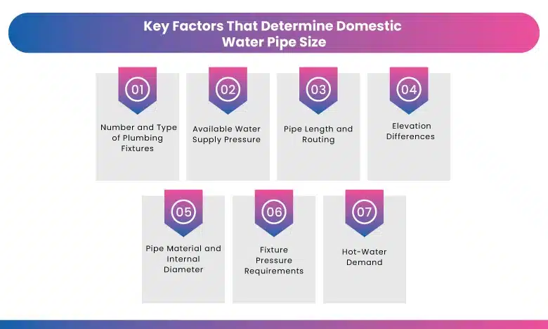
Before selecting pipe diameters, MEP engineers should evaluate several design inputs.
1. Number and Type of Plumbing Fixtures
The number and type of fixtures influence the expected water demand.
Typical residential fixtures and appliances include:
- Toilets
- Bathroom faucets
- Showers and bathtubs
- Kitchen sinks
- Dishwashers
- Washing machines
- Utility sinks
- Refrigerators with water connections
- Outdoor hose bibbs
Different fixtures have different flow requirements and usage patterns. Engineers should use the applicable fixture-unit values, demand method, and project requirements rather than treating every fixture as an equal load.
2. Available Water Supply Pressure
The pressure available at the service connection determines how much pressure is available to move water through the home’s piping network.
Engineers should establish the design supply pressure using reliable project or utility information. Where appropriate, pressure should be measured under relevant conditions because static pressure alone may not represent the pressure available when water is flowing.
The available pressure must be sufficient to overcome system losses while maintaining the required pressure at the most demanding fixture.
3. Pipe Length and Routing
Longer pipes generally create greater friction losses. Multiple bends, fittings, valves, and other components also contribute to pressure loss.
For example, a second-floor shower located far from the water entry point may have a more demanding hydraulic path than a ground-floor faucet close to the main supply.
The design should account for the actual piping route, including the relevant equivalent lengths or fitting-loss calculations used in the selected sizing method.
4. Elevation Differences
Elevation affects available water pressure. Water supplied to fixtures above the service connection requires additional pressure to overcome the vertical rise.
For residential projects, this can be particularly important when serving:
- Second-floor bathrooms
- Third-floor fixtures
- Elevated showerheads
- Homes with water supply equipment located below the occupied floors
The engineer should evaluate the hydraulically most demanding fixture rather than assuming all fixtures have the same pressure conditions.
5. Pipe Material and Internal Diameter
Common residential domestic water piping materials include copper, PEX, and CPVC, subject to project specifications and local code approval.
Nominal pipe size does not necessarily equal the actual internal diameter. Internal diameter and hydraulic characteristics can vary by material and pipe series.
Therefore, the selected pipe material and its corresponding sizing data must be used in the hydraulic calculations.
6. Fixture Pressure Requirements
Each fixture or appliance has operating requirements that influence the design.
The engineer should identify the minimum pressure required by the applicable fixture, appliance, or equipment manufacturer. The system must maintain the necessary pressure at the point of use under the design flow condition.
Where a fixture has a higher pressure requirement than other fixtures, it may determine the critical path for sizing the system.
7. Hot-Water Demand
Hot-water piping requires consideration of fixture demand, the water heater location, pipe routing, and the hot-water distribution arrangement.
Long hot-water runs can increase the time users wait for hot water. Pipe sizing alone does not resolve this issue; routing, insulation, recirculation design where applicable, and water-heating strategy also matter.
Step-by-Step Process for Sizing Domestic Water Pipes
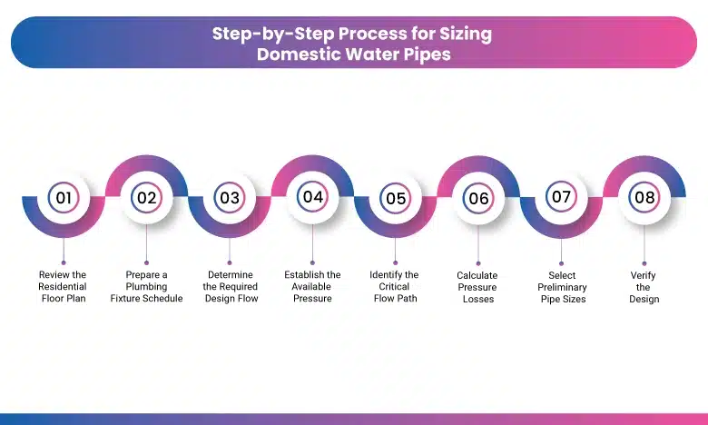
MEP engineers can follow a structured process to size the domestic water distribution system for a single-family home.
Step 1: Review the Residential Floor Plan
Start by reviewing the architectural drawings and identifying the number of floors, bathrooms, kitchen, laundry area, utility spaces, and outdoor water connections.
The floor plan helps establish where the fixtures are located and how the water supply can be routed through the building.
At this stage, identify potential constraints such as narrow wall cavities, floor joists, ceiling spaces, and long distances between the service entry and fixtures.
Step 2: Prepare a Plumbing Fixture Schedule
Create a list of the fixtures and appliances that require domestic water.
A fixture schedule helps the engineer identify the expected demand and determine which fixtures are supplied by each branch.
For example, a home might have separate branches serving the kitchen, first-floor bathroom, second-floor bathrooms, laundry area, and outdoor hose connections.
The final schedule should reflect the actual project rather than relying on a generic house layout.
Step 3: Determine the Required Design Flow
Use the applicable plumbing code’s approved sizing method to establish the probable demand for the system.
Depending on the adopted code and design method, engineers may use water-supply fixture units and corresponding sizing tables or an approved calculation approach to estimate demand.
It is important to distinguish between the sum of individual fixture flow rates and probable simultaneous demand. Residential systems are generally designed using an appropriate demand method rather than assuming that every fixture operates at maximum flow at the same time.
Step 4: Establish the Available Pressure
Determine the available water pressure at the building supply connection.
The design should account for the actual source conditions and any pressure losses associated with the service arrangement, meter, backflow prevention device, pressure-reducing valve, filter, or other equipment where present.
If the available pressure is inadequate for the home’s demand and elevation, the engineer may need to evaluate an appropriate pressure-boosting or pressure-management solution.
Step 5: Identify the Critical Flow Path
The critical path is the route from the water source to the fixture or group of fixtures that creates the most demanding pressure condition.
It is not always the physically longest pipe route. A shorter route serving a high-demand fixture can be more demanding because of its flow requirement, fittings, equipment, or required fixture pressure.
For a two-story home, the critical path might lead to an upstairs shower or another fixture with a demanding combination of flow, elevation, and pressure requirements.
Step 6: Calculate Pressure Losses
Evaluate the pressure losses along the critical path.
The pressure budget should account for relevant losses from:
- Pipe friction
- Fittings and valves
- Water meters and backflow prevention devices
- Filters and other equipment
- Elevation changes
- Required pressure at the fixture
A simplified pressure relationship is:
Available supply pressure = elevation loss + friction and equipment losses + required residual fixture pressure
This relationship helps engineers determine whether the proposed piping system can deliver the required performance.
Step 7: Select Preliminary Pipe Sizes
Use the applicable code tables or an accepted hydraulic calculation method to select preliminary pipe diameters.
The sizing process should consider the demand carried by each pipe section, the pipe material, the available pressure, and the permitted design conditions.
Main supply pipes generally serve more downstream demand than individual fixture branches. Consequently, the pipe size may change as the distribution system divides into smaller branches.
Step 8: Verify the Design
Check that the selected sizes provide the required flow and pressure at the critical fixtures.
If the calculated pressure is insufficient, revise the pipe sizes or investigate other design factors, such as the service pressure, equipment losses, route length, or pressure-management arrangement.
The engineer should then review the complete distribution network, not just the critical path, to confirm that the remaining branches are also adequately sized.
How to Size the Main Water Supply and Branch Pipes
Different sections of a residential water system serve different purposes, so they should not automatically use the same pipe diameter.
Main Water Service
The service pipe supplies water from the source to the home. Its size depends on the design demand, available pressure, service length, meter and equipment losses, and applicable sizing requirements.
A service pipe that is too small can affect the performance of the entire home.
Main Distribution Pipe
The main distribution pipe carries water to multiple branches. Its demand depends on the fixtures and branches it supplies.
As the distribution network divides, downstream sections may require smaller pipe sizes because they serve fewer fixtures. The final sizes must still be determined through the selected sizing method.
Branch Pipes
Branch pipes supply groups of fixtures, such as a bathroom group, kitchen, or laundry area.
The engineer should evaluate the demand carried by each branch and verify pressure at the fixtures it serves.
Individual Fixture Supply Lines
Individual fixture connections must provide the flow and pressure required by the fixture or appliance.
Manufacturers’ connection requirements and applicable plumbing code provisions should be checked when determining the final supply arrangement.
Hot-Water Distribution Pipes
Hot-water pipe sizing should be coordinated with the water heater, fixture demand, and distribution layout.
Where a recirculation system is proposed, its design requires additional consideration beyond sizing the cold-water supply.
Example: Sizing Water Pipes for a Two-Story Home
Consider a hypothetical two-story, single-family home with three bathrooms, a kitchen, a laundry area, and outdoor hose connections.
The domestic water system may include:
- One incoming water service
- A main distribution line
- Branches serving the bathrooms and kitchen
- Separate hot- and cold-water distribution
- A water heater and associated connections
- Fixture supply lines
The engineer begins by reviewing the fixture schedule and determining probable demand using the applicable sizing method. Next, the available supply pressure and the elevation of the second-floor fixtures are evaluated.
The critical path is then identified, and pressure losses are calculated for the pipe route, fittings, valves, and relevant equipment. Preliminary pipe sizes are selected and checked to verify that the required pressure remains available at the critical fixture.
The actual pipe diameters cannot be determined from the number of bathrooms alone. The final sizes depend on the applicable code, pipe material, fixture demand, supply pressure, pipe routing, elevation, and equipment losses.
This is why MEP engineers should perform project-specific calculations instead of applying one standard pipe-size schedule to every single-family home.
How to Account for Simultaneous Fixture Use
A residential plumbing system must accommodate realistic periods of overlapping demand.
For example, a household might use a shower while a kitchen faucet is running and a washing machine is filling.
The combined demand on the main supply can be significantly greater than the demand from any one fixture. However, assuming that every fixture will always operate simultaneously at maximum flow can also lead to inappropriate sizing.
MEP engineers use the applicable code’s demand method to estimate probable usage and select pipe sizes accordingly.
The design should then be checked to ensure that the most demanding fixtures receive adequate flow and pressure during the intended operating conditions.
Common Mistakes in Residential Water Pipe Sizing
Using the Same Pipe Size for Every Section
The main supply, bathroom branches, and individual fixture connections do not necessarily carry the same demand. Applying one diameter throughout the system can result in inefficient or inadequate sizing.
Ignoring the Second-Floor Pressure Requirement
Elevation reduces the pressure available at higher fixtures. A design that works at ground-floor faucets may not provide adequate pressure upstairs.
Relying Only on Static Water Pressure
Static pressure does not show the full pressure loss that occurs when water flows through the system. The design should consider the available pressure under relevant flow conditions.
Overlooking Equipment and Fitting Losses
Meters, valves, filters, backflow prevention devices, and other components can contribute to the total pressure loss. Ignoring these losses can lead to an inaccurate assessment of available fixture pressure.
Selecting Pipe Sizes Without Checking the Material
Different pipe materials and product series can have different internal diameters and hydraulic characteristics. The engineer should use the correct data for the selected piping system.
Oversizing Pipes Without a Design Basis
Larger pipes may reduce friction losses, but they can increase material costs and water volume. Pipe sizing should be based on calculated demand and pressure requirements rather than an assumption that bigger pipes are always better.
Failing to Coordinate the Piping Route
A hydraulically adequate pipe can still be difficult to install if it conflicts with structural framing, ducts, electrical services, or architectural features. Pipe routing should be reviewed during design development.
How Revit MEP and BIM Support Residential Plumbing Design
Revit MEP and BIM workflows can help engineering teams develop coordinated domestic water layouts for single-family homes.
Depending on the project scope and modeling standards, BIM can support:
- Modeling domestic cold- and hot-water piping
- Coordinating pipes with walls, floors, and structural framing
- Reviewing plumbing routes and fixture connections
- Identifying clashes with HVAC ducts and electrical systems
- Coordinating water heater locations and connections
- Preparing coordinated plumbing drawings
- Updating documentation when layouts change
BIM supports layout development and coordination, but it does not automatically guarantee correct hydraulic sizing. Engineers must still complete the required calculations and verify the design against the applicable code and project criteria.
Residential Plumbing Codes and Design Requirements in the United States
Residential plumbing design requirements can vary by state and local jurisdiction. The applicable code may depend on the adopted plumbing code, state amendments, local requirements, and the specific building type.
Before finalizing domestic water pipe sizes, MEP engineers should confirm:
- Which plumbing code and edition the jurisdiction has adopted
- The approved water pipe sizing method
- Fixture-unit values and demand calculation requirements
- Permitted pipe materials
- Required fixture pressures and flow conditions
- Water service and pressure-control requirements
- Applicable product listings and installation requirements
Engineers should not assume that one state’s code provisions or sizing tables apply throughout the United States. The design must follow the requirements applicable to the project location.
How MVN Engineering Supports Residential Plumbing Design
MEP firms handling single-family residential projects may need reliable engineering and BIM production support to manage drawings, modeling, coordination, and documentation workloads.
MVN Engineering Services supports MEP firms with plumbing design and related production services, including:
- Domestic water piping layouts
- Hot- and cold-water distribution modeling
- Plumbing drafting and construction documentation
- Revit MEP modeling
- Plumbing system coordination
- MEP clash detection
- Drawing updates based on markups and design revisions
- BIM coordination and production support
By working with the project team’s drawings, design criteria, and established workflows, MVN can support residential MEP projects that require coordinated plumbing documentation and additional production capacity.
Conclusion
Sizing domestic water pipes for single-family homes requires a project-specific evaluation of fixture demand, available supply pressure, pipe length, elevation, material characteristics, and equipment losses. The goal is to provide sufficient water flow and pressure at the required fixtures without unnecessary oversizing.
For MEP engineers, a structured process that includes fixture-demand calculations, critical-path analysis, pressure-loss evaluation, and design verification helps produce reliable residential water distribution systems. Coordinating the piping layout with architectural and structural elements also helps reduce installation conflicts and avoidable design changes.
By combining sound hydraulic calculations with coordinated Revit MEP documentation, engineering teams can develop practical domestic water systems that meet the needs of the home and the requirements of the applicable jurisdiction.